A Welding Pallet is the working platform that positions, supports, and transfers components during welding. It often carries clamps, locating pins, fixtures, and partially assembled frames. In automated cells, the pallet moves between loading, welding, inspection, and unloading stations. Its purpose is practical: keep every part in the correct place while heat and movement challenge accuracy.
John C. Villafuerte, author of Modern Welding Technology, offers a useful principle: “Fixtures must control position, not merely hold parts.” This idea explains how a Welding Pallet works. Locators establish reference points, while clamps resist shifting during welding. The base must also tolerate spatter, heat, vibration, and repeated handling. A well-designed pallet can reduce setup time, improve weld consistency, and support safer operator movement. Small details matter. A worn pin can create a large dimensional error.
This article examines pallet construction, fixture layout, operating steps, and common maintenance concerns. It also considers how pallets connect with robotic welding systems and production traceability. In real workshops, results are rarely perfect. Distortion, poor cleaning, or an incorrectly adjusted clamp can still affect quality. That weakness deserves attention. A pallet does not correct every process problem. It only creates a stable foundation for a controlled welding process. Readers should compare the design with their material, joint geometry, load requirements, and production environment before choosing a system.
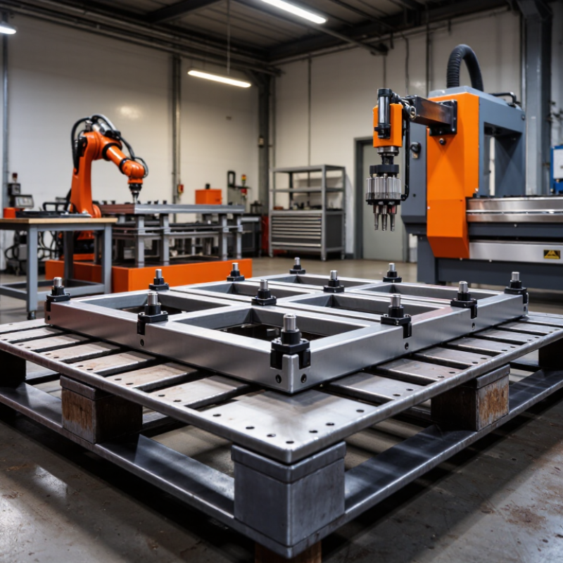
A welding pallet is a rigid, reusable work surface designed to hold metal parts during fabrication. It usually contains a flat steel plate, accurately positioned holes, slots, or reference points. These features allow clamps and stops to secure components at repeatable locations. Its main purpose is simple: keep parts stable, aligned, and accessible while welds are applied.
A fabricator places the pallet on a sturdy table or support frame. Clamps then press the workpieces against fixed stops. This arrangement limits movement caused by heat and shrinkage. It also helps maintain consistent angles between parts. For example, a small frame can be positioned against two stops before short tack welds are added. After checking the diagonals, the operator can complete the welds with fewer adjustments.
In daily use, the pallet must remain clean and reasonably flat. Spatter around a locating hole can shift a part by several millimeters. That error may seem minor, but it can distort an entire assembly. Operators should inspect clamps, remove debris, and verify critical dimensions before welding. Experience shows that even a well-made pallet cannot correct poor setup. I have found that checking the first assembled piece saves more time than correcting a full batch later. No pallet is perfect, especially after repeated heating. Its condition, fixture design, and operator judgment all affect the final result.

A welding pallet is a rigid fixture base that holds parts in repeatable positions during fabrication. Its main components include a steel pallet plate, locating pins, stops, clamps, and replaceable wear blocks. Machined holes or slots create a datum grid. This grid controls height, angle, and spacing. A grounded contact point also helps maintain a stable welding circuit. Small details matter. One loose pin can shift an entire frame.
Structural design balances stiffness, access, and thermal movement. Thick plates resist bending, while ribs beneath the pallet reduce deflection without excessive weight. Designers often add lifting pockets and drainage openings. These features support safer handling and easier cleaning. The American Welding Society’s welding design guidance stresses dimensional control and joint access as major quality factors. The 2023 U.S. Bureau of Labor Statistics report counted over 400,000 welding-related workers, showing how widely repeatable fixture systems support production. Still, a pallet that is too rigid can trap heat and increase distortion. That problem is easy to underestimate.
Tips: Keep locating pins replaceable. Check flatness before each production run. Leave torch and inspection access around every joint. Record pallet temperature when parts vary noticeably. A simple log can reveal patterns. Do not trust appearance alone; measure critical points with a calibrated gauge. In practice, I would also review clamp positions after the first few welds, because the original setup may look correct but behave poorly under heat.
| Design Dimension | Main Component | Typical Data or Structural Characteristics | Role in Welding Operation |
|---|---|---|---|
| Basic Definition | Welding Pallet | A rigid, reusable fixture base used to position, support, and transport workpieces during welding and assembly. | Creates a repeatable reference surface and helps maintain consistent part location from one cycle to the next. |
| Primary Structure | Base Plate or Welded Frame | Usually made from steel or other weldable structural metal. The frame may use plates, square tubing, ribs, or boxed sections to increase stiffness. | Supports the workpiece, fixture elements, and welding forces while limiting deflection. |
| Reference System | Locating Surface and Datum Points | Machined pads, datum faces, holes, pins, or slots establish the X, Y, and Z reference directions for the assembly. | Defines the exact position of components and reduces variation caused by manual measurement. |
| Positioning | Locating Pins and Stops | Fixed or replaceable pins and stops are placed at selected contact points. Round pins, diamond pins, and adjustable stops are common fixture elements. | Restricts unwanted movement while allowing the workpiece to be loaded and removed efficiently. |
| Clamping | Manual, Pneumatic, or Hydraulic Clamps | Clamping devices apply controlled force to hold parts against the locating surfaces. The required force depends on part mass, weld shrinkage, and welding position. | Prevents lifting, shifting, vibration, and joint opening during tack and final welding. |
| Modularity | Grid Holes, Slots, and Mounting Interfaces | Modular pallets may use a regular hole or slot pattern for attaching interchangeable locators and clamps. Common grid spacing is selected according to the fixture size and application. | Allows one pallet to accommodate multiple product variants and simplifies fixture changeover. |
| Dimensional Accuracy | Machined Datum Features | Critical reference areas are machined after fabrication when necessary. Flatness, hole location, and squareness should be verified against the required assembly tolerance. | Improves repeatability and helps ensure that welded assemblies meet drawing requirements. |
| Stiffness | Reinforcement Ribs and Crossmembers | Ribs, gussets, and crossmembers increase bending and torsional rigidity without requiring an excessively thick base plate. | Maintains fixture geometry under workpiece weight, clamping loads, and thermal forces. |
| Thermal Design | Heat-Resistant Contact Areas | Contact surfaces are designed to tolerate welding heat, spatter, and repeated thermal cycling. Clearance may be provided around weld seams and heat-affected areas. | Reduces distortion, prevents interference with the weld torch, and extends fixture service life. |
| Welding Access | Openings and Tool-Clearance Zones | Cutouts, reliefs, and access windows provide space for the torch, electrode, clamps, and inspection tools while maintaining adequate structural support. | Enables the required weld angles and helps avoid collisions between the fixture and welding equipment. |
| Grounding | Electrical Grounding Path | A dedicated, clean grounding connection is preferred over relying on movable fixture joints or painted surfaces. | Provides a stable return path for the welding current and reduces arcing at unintended contact points. |
| Material Selection | Structural Steel or Alloy Components | Material selection considers yield strength, weldability, thermal expansion, wear resistance, corrosion exposure, and machining requirements. | Balances load capacity, dimensional stability, fabrication cost, and maintenance needs. |
| Operating Cycle | Load, Locate, Clamp, Weld, Unclamp, Unload | The workpiece is placed against the datums, secured by clamps, welded in a planned sequence, released, and removed for inspection. | Provides a repeatable workflow that supports consistent quality and predictable cycle times. |
| Distortion Control | Balanced Clamping and Weld Sequence | Locators and clamps are distributed to control gaps and restraint. Welding may alternate between sides or sections to balance heat input. | Limits angular distortion, dimensional drift, and residual stress in the finished assembly. |
| Safety and Maintenance | Spatter Protection, Inspection, and Cleaning | Anti-spatter measures, accessible clamp handles, regular removal of weld debris, and periodic checks of pins, holes, and flatness are recommended. | Maintains safe operation, reliable positioning, and long-term fixture accuracy. |
Awelding pallet is a rigid work surface that supports parts during fabrication. It usually contains a grid of holes, slots, or locating points. These features help welders position plates, tubes, and brackets accurately. The pallet also keeps assemblies at a comfortable working height. That small improvement can reduce awkward reaching and repeated repositioning.
In practical shop work, the pallet works with stops, clamps, and locating pins. A fabricator places each component against fixed reference points. Clamps then hold the parts while tack welds secure the initial shape. The setup limits movement caused by heat. It also makes repeated assemblies more consistent. Fit-up becomes easier to inspect. Measurements can be checked before the final weld begins.
Heat still changes metal. The pallet cannot remove every distortion risk. A useful setup may include balanced clamping and a planned welding sequence. Some pallets also improve access by allowing the assembly to rotate or shift. Before welding, operators should check the surface for spatter, damage, and contamination. They should never assume the pallet provides electrical grounding. Continuity must be verified through a suitable grounding path. In my experience, a quick check prevents confusing arc behavior and protects the work area. The fixture may look precise, yet careless loading can defeat that precision. Small gaps matter. Regular inspection keeps the reference points dependable over time.
A welding pallet is a rigid fixture that holds parts in a repeatable position during welding. It usually has a flat steel surface, locating holes, stops, and adjustable clamps. The welder places components against these reference points, then secures them before striking an arc. According to the International Federation of Robotics’ World Robotics 2024 report, 541,302 industrial robots were installed globally in 2023. This growth increases the need for accurate, repeatable fixturing in manual and automated cells.
Step-by-step operation begins with cleaning the pallet surface and checking its flatness. Even small spatter can shift a part. The operator then loads the base component against fixed stops, followed by secondary parts. Clamps should apply firm pressure without distorting thin sheet metal. A quick diagonal measurement helps confirm squareness. It is easy to skip this check. That shortcut can create costly rework.
The welder next confirms the joint gap, torch access, grounding path, and weld sequence. Short tack welds hold the assembly while heat is distributed across opposite sides. After inspecting the tacks, the operator completes the welds in a controlled pattern. AWS D1.1-based procedures commonly require qualified personnel, documented parameters, and visual inspection criteria for structural work. When cooling is complete, clamps are released, and the assembly is checked for distortion. The pallet is then brushed, inspected, and reset for the next cycle. In practice, fixture marks can become confusing, so clear labels and a simple loading sheet are worth the effort.
A welding pallet is a rigid, reusable platform for positioning parts during fabrication. It usually includes a flat steel surface, locating holes, slots, or replaceable fixtures. Welders place brackets, tubes, panels, or frames against these reference points. Clamps then hold each component while the weld is made. This process improves repeatability and reduces measurement time between assemblies.
Common applications include structural frames, machine guards, agricultural equipment, cabinets, and pipe supports. A pallet is especially useful when a workshop produces similar parts in small or medium batches. It can keep a rectangular frame square while heat pulls one corner inward. It also gives welders better access to joints and helps maintain consistent gaps. In practice, perfect alignment is not guaranteed. Poorly cleaned holes or worn stops can introduce small errors.
Selection requires more than checking the pallet’s overall size. Consider the heaviest assembly, expected heat input, and available lifting equipment. A thick, stress-relieved surface may resist distortion better during repeated welding. Hole spacing should match the fixture system and the part dimensions. Look for secure clamping points, drainage for spatter and liquids, and enough clearance for torches. Inspect flatness regularly. A simple test with a precision straightedge can reveal high spots. Mobility may also matter, but wheels need reliable locks. A pallet that is easy to move may be less stable under heavy side loads. That trade-off deserves careful review before purchase.